
5 Prong Trailer Wiring Diagram
The wiring diagram for five pin trailer plugs shows the arrangement of electrical components in a specific way to ensure proper connection and function. The diagrams are typically presented in four parts: the main harness, the center connector, the ground wire, and the accessory wiring.

4 Blade Trailer Plug Wiring Diagram
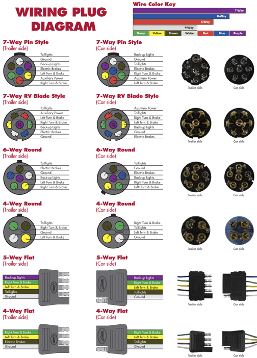
At a minimum, all trailers need at least 4 functions: Tail lights, Brake lights, Left & Right signals. 4 wires will give these functions, so the simplest scheme is a 4-pin connector. The most common 4 wire connector is the 4-Pin Flat Connector as shown here.
5 pin trailer connector diagram
A simple diagram on wiring a 5 pin trailer harness.LIKE AND SUBSCRIBE
Trailer Light Connector Wiring
There are three common trailer plug types - 5 pin, 4 pin and 7 pin. The 5 pin plug is the most commonly used and is found on many smaller trailers. It is important to correctly identify which plug type is being used as the wiring process will differ depending on the plug type. Gathering the Necessary Tools

Pippa Schema Trailer Light Wiring Diagram 5 Wire Generator Interlock
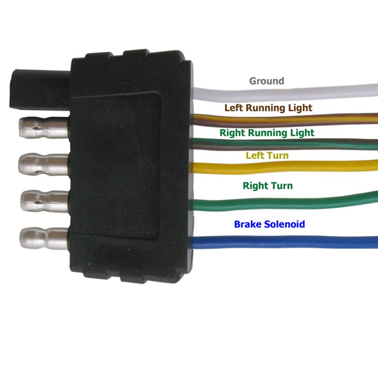
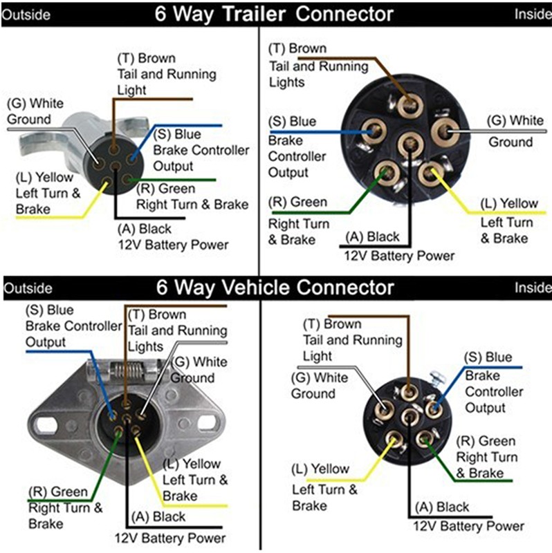
The 5 pin trailer wiring harness is color coded so that you can easily identify which wire is for what purpose. The white wire is the ground wire and should be connected to the negative terminal of the battery. The other four wires are red, yellow, green and brown. The red wire is the power wire and should be connected to the positive terminal.

Standard Wiring Diagram For Trailer Plugs
5-Pin Trailer Wiring Diagram. In this 5-pin trailer wiring diagram above, you can see that the first wire is the ground wire (white). The second wire (green) to originate from the connector is responsible for the right signal. The third (brown) wire is the one that is responsible for the taillights. These are also connected to the side to.
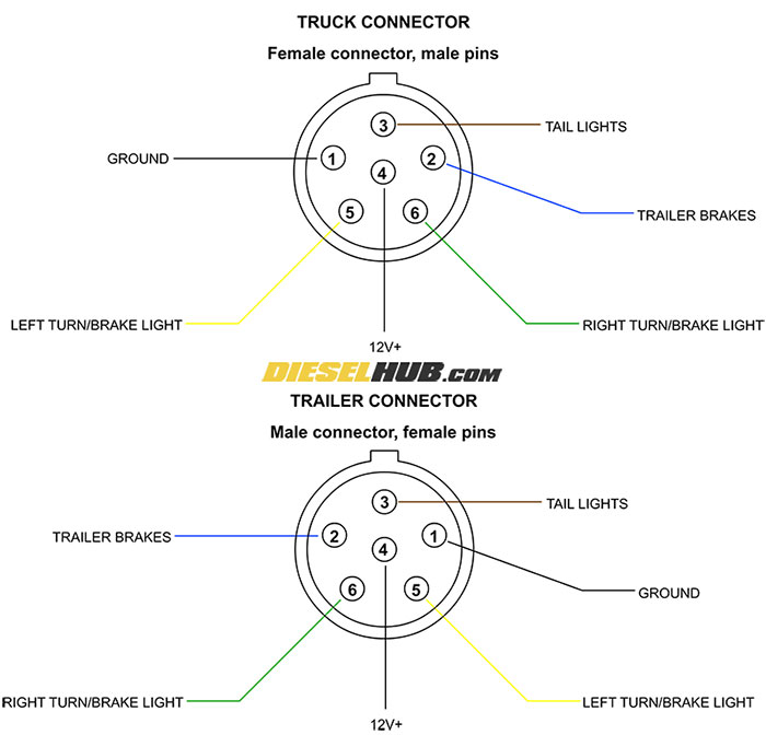
Wiring Diagram For Trailer Plug On Truck
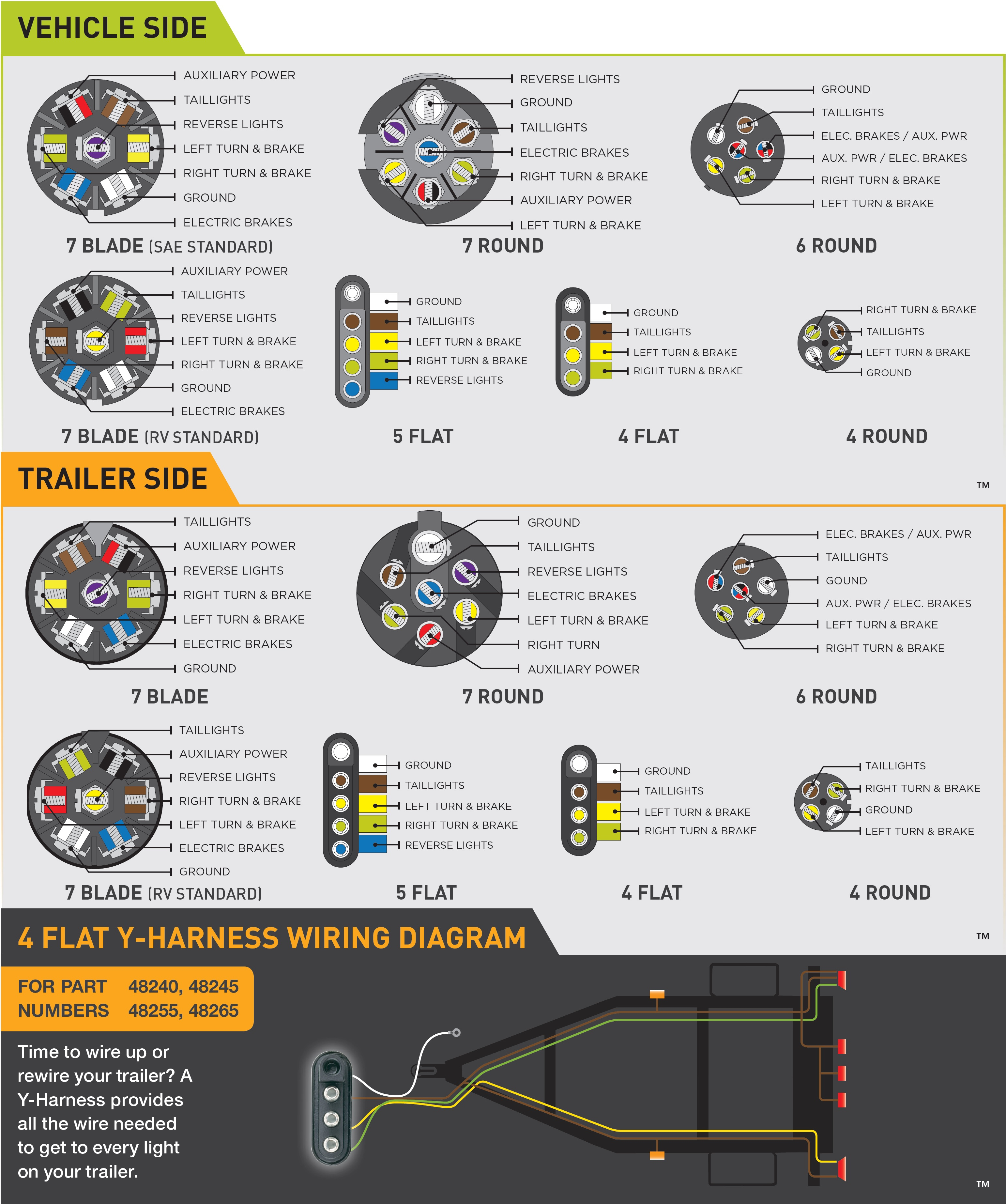
5-Way Connectors 5-Way connectors are available allowing the basic hookup of the three lighting functions (running, turn, and brake) and, besides the ground, one pin is available to provide support for another function. Typically the 5-Way Flat is used for trailers with surge brakes or hydraulic brakes.
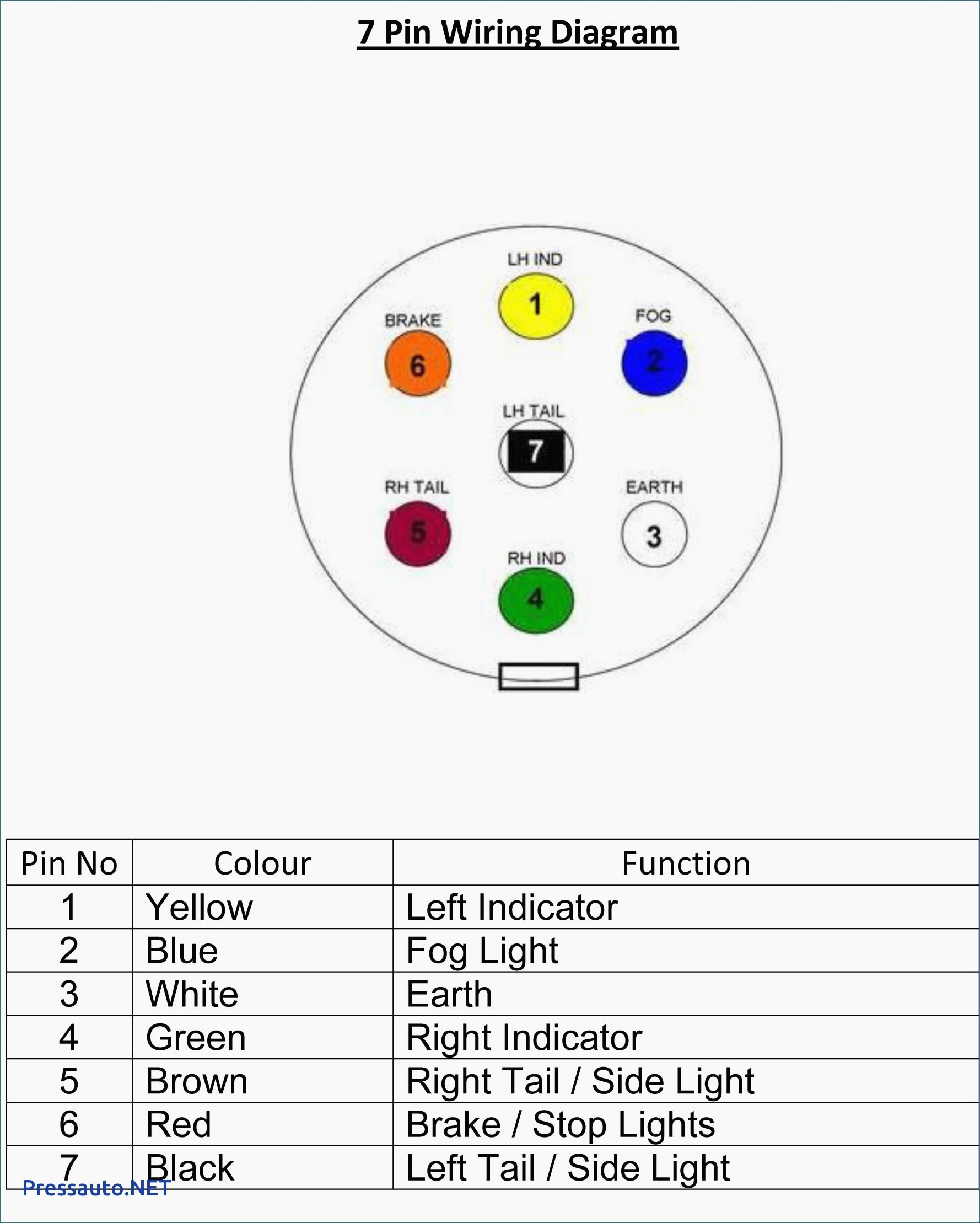
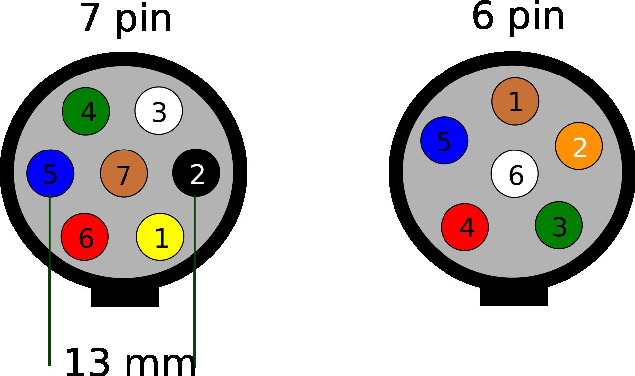
7 point trailer plug wiring diagram
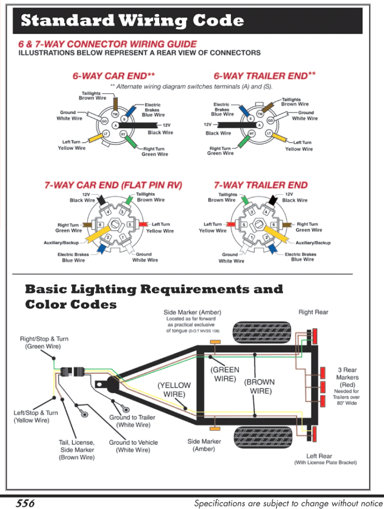
7 Pin (AS 4735) for Heavy Duty Vehicles. This connector is based on both SAE J560 and ISO 1185 and is providing either 12V, 7 x 40A or 24V, 7 x 20A. The voltage varies from vehicle to vehicle. Pin 1 - White - Earth. Pin 2 - Black - Left hand rear , clearance and marker. Pin 3 - Yellow - Left hand turn.
5 Way Trailer Wiring Diagram
A 5 pin trailer connector diagram is a simple illustration that shows how to wire up the 5-pin connectors on the back of a tow vehicle to connect it to a trailer. It shows the wires in the order they should be connected, as well as where they should be connected. The diagram also shows how the trailer should be wired, including the ground wire.
5 Way Trailer Light Wiring Diagram
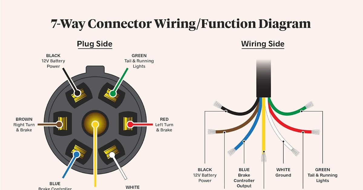
Trailer Wiring Made Easy with 7-Way Round Trailer Plug If you're planning a trip with your trailer, you'll want to make sure that your wiring is up to par. A faulty wiring system can cause all kinds of headaches, from stoplights that don't work to turn signals that won't signal - and that's not even
Hopkins Trailer Connector Wiring Diagram Wiring Diagram
Understanding the wiring diagram for a 5 pin trailer plug is important for anyone who tows trailers for work or recreation. The 5 pin trailer plug is a standard type of connector used on many trailers and recreational vehicles. This plug features five round pins which each have a specific purpose for connecting the trailer to the vehicle.
Wiring Diagram For A 5 Pin Trailer Plug Wiring Diagram
One of the most common types of trailer wiring is the 4 pin 5 wire system. This configuration allows you to connect your trailer lights to your vehicle's electrical system, providing the necessary power and control. In this step-by-step guide, we will walk you through the process of wiring a trailer using the 4 pin 5 wire system.

7 Way Trailer Plug Wiring Instructions
A 5 pin wiring diagram is a diagram that shows how to wire a five-pin connector. It includes all the electrical connections needed for a trailer connection, including the ground, running lights, brake lights, left-hand turn, and right-hand turn signals. It also shows the connection points between the trailer and the tow vehicle.

5 Pin Trailer Wiring
Watch on Two Types of Custom Wiring Custom Wiring Harnesses A custom wiring harness has multiple plugs that are used to 'T' into the vehicle's taillight assembly, drawing power directly from the taillights or from a direct battery connection and providing a standard trailer light wiring connector.

5 Pin Round Trailer Plug Wiring Diagram
The five pins are typically labeled for their function, with each one providing a different signal or power source to ensure the trailer's brakes, turn signals, reverse lights, and other features work as intended.
Round Trailer Plug Diagram Max Blog
The 5 pin trailer connector diagram consists of five pins, each serving a specific purpose. These pins are labeled as per the international standard and are designed for specific electrical connections, including tail lights, brake lights, turn signals, and ground.